

The electricity sector in India has seen rapid growth over the past few decades. With installed capacity of 373 GW, India is able to meet the demand for electricity. As generation capacity has grown, an extensive network of transmission lines has also been developed for evacuating power produced by different electricity generating stations and distributing it across India to all consumers.
Controlled switching, a technique to improve life expectancy of assets and improve system stability, has gained importance in the transmission system after successful utilization in 765kV and 400kV system. In this blog post, we will see how Controlled Switching techniques are being used for Transformers, Reactor, Capacitor Bank and Transmission line applications.
Controlled switching
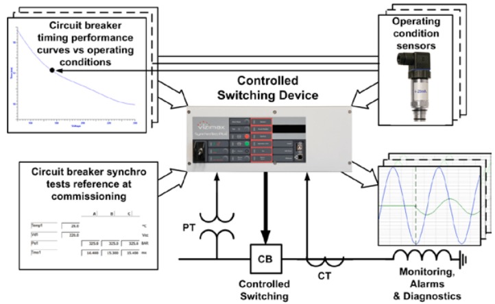
Controlled Switching technology is based on the synchronization of the mechanical operation of Circuit Breaker with a specific target point on an associated voltage or current waveform in order to switch it at the ideal electrical instant that mitigates undesired power system disturbances and stress on the electrical assets.
Circuit Breaker operation & its relation with Controlled Switching device
The performance of a CSD depends greatly on the consistency of CB mechanical characteristics and dielectric behavior. The CSD accurately predict the value of CB timing under all possible circumstances to perform controlled switching efficiently.
Controlled Switching of Shunt Reactors
Transmission utilities deploy bus and line reactors to address voltage rise due to highly loaded transmission lines. Without any mitigation technique, a shunt reactor that is randomly de-energised statistically leads to systematic re-ignition of the CB with possible damage of the nozzle system. Controlled switching of shunt reactors has been widely used to eliminate the re-ignition when opening the circuit breaker.
The main issues with Random switching of Shunt Reactors are
- Re-ignition of Current during De-energisation of Shunt Reactor
- Current asymmetry during Energisation of Shunt Reactor
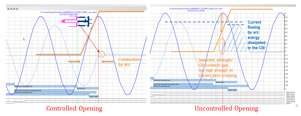
Controlled opening of shunt reactor
Using Controlled switching device, it is possible to control the moment the current is interrupted (TgtAng) as well as the arc duration (ArcTm) to avoid re-ignition. The electrical target opening angle of the CB (TgtAng) can be synchronized on the load current or on the bus voltage. For the Reactor the best electrical closing and opening instants are when the voltage is at its crest (peak).
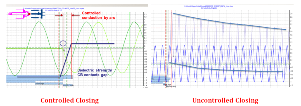
Current asymmetry during energisation
Shunt reactors being energised at voltage zero produce their highest current asymmetry. It has been seen that a reactor is a device that opposes the current variation, and consequently, the current lags the reactor voltage by 90°. This means that in order to eliminate switching transients, the best electrical closing and opening instants are when the voltage is at its crest (peak).
Controlled Switching of Capacitor Bank
Controlled switching of capacitor banks using a CSD product has been widely used in order to reduce inrush current when closing the circuit breaker. Capacitor banks are used for voltage regulation and filter applications. Mechanically Switched Capacitor systems (MSC) are widely used in SVC and STATCOM applications with additional requirements for fast switching. Since a capacitor opposes to rapid voltage changes, the best moment to energize this device using a circuit breaker is when its voltage is equal to the grid voltage.

When switching each CB pole at zero voltage, the current in the discharged capacitor is established gradually to its nominal value rapidly: this switching strategy avoids high inrush current and voltage disturbances. Switching the CB at any other point would cause inrush current since capacitors oppose to sudden voltage changes.
Effect of Switching the Circuit Breaker at wrong moment
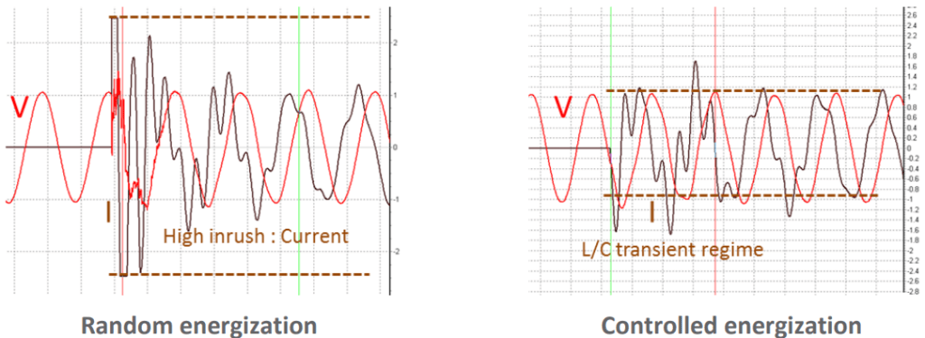
Above figure illustrates the switching of a discharged wye-grounded capacitor bank at random moment (left) compared to closing at zero crossing of the source voltage (right). It can be seen on the left that the peak inrush current is almost 4 times the nominal current value. There is also switching transients on the voltage waveform during the first cycle that are propagated everywhere on the network. This could have been worst by switching the capacitor bank at maximum voltage. However, by switching the CB close to voltage zero crossing (right figure), the inrush current is eliminated and the switching transients on the voltage are minimized.
Conclusion
Random switching of circuit breakers without proper correlation with system voltage or current always causes unwanted voltage stresses in Power Transmission System. These disturbances and over voltages may result in equipment failure or reduction in their useful lifespan. These disturbances also cause issues in power system stability such as high amplitude & high frequency disturbances leading to system outage with unexpected relay operations.
Controlled switching is one of best technique available today to mitigate re-ignitions due to over voltages as well as inrush currents during energisation of the shunt reactor. Controlled switching is basically an additional capability added to standard circuit breaker so that the circuit breaker operates at precise electrical moment.
Summary
SCOPE marketed SynchroTeq Plus and SynchroTeq MV are effective at resolving problems such as inrush current and reignition observed in number of assets, thereby prevent the accumulation of stress on the equipment which can cause major failures.
For more information on SCOPE marketed Controlled Switching Devices, please visit https://www.scopetnm.com/protection-solutions/controlled-switching-device or write to us at marketing@scopetnm.com.

One Reply to “”