

In our previous blog, we discussed the technique of controlled switching, a widely used technique to improve the life expectancy of assets and system stability. We had seen how the life span of reactor and capacitor bank assets can be extended through controlled switching.
In this blog post, we will continue our discussion on controlled switching by sharing our knowledge on how this critical technique can be used to improve life span and system stability of power transformers.
Complex Transmission System
Data from the Central Electricity Authority show that the transmission sector has grown manifold over the last few decades. At the end of the 6th Five Year Plan (1980-1985), 52,034 Ckm of transmission lines (up to 400 kV) and 46,621 MVA of substation capacity was operational. As on August 2020, cumulative capacity of transmission lines is 4,28,582 Ckm of transmission linces and 9,81,503 MVA of substation capacity is operational. Furthermore, transmission assets today include much higher voltage class such as 800 kV HVDC, 500 kV HVDC and 765 kV HVDC. This showcases the complexity of the present transmission network and the need for effective techniques to improve life span and system stability of all transmission assets, including power transformers.
Controlled Switching of Power Transformer
The main issue to be addressed with the uncontrolled switching of power transformer is high inrush current.
When a high voltage power transformer is de-energised, it keeps some residual flux in their iron cores, which may affect the inrush current magnitude at the next energisation, depending on the energisation instants.
As transformers are normally energised by arbitrarily closing the circuit breaker contacts with the system voltage being applied on the transformer windings at random instants, this switching operation may introduce an asymmetrical magnetic flux in the windings, driving the transformer core into saturation.
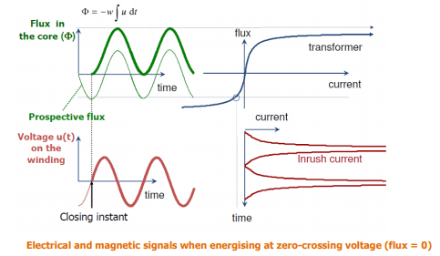
As soon as the magnetic flux value goes over the saturation level (called the saturation knee), the current will increase faster than the flux and extra current will then be needed to further increase the magnetic flux density.
This will produce inrush current whose magnitude depends mainly on the transformer core characteristics, the closing moment on the network voltage (point on wave), and the amount of residual flux.
Therefore, the worst case with respect to the higher inrush current is Energising Power Transformer at zero crossing voltage.
Techniques used for controlled closing of Power Transformer
Fast closing energising strategy
This strategy is based on the use of an Individual Pole Operated Circuit Breaker (IPO CB). One CB pole is closed first at the making instant that produces a magnetic flux equal to the residual flux present in the corresponding transformer core.
The two other CB poles are then closed simultaneously at the first voltage zero-crossing of the first phase that was closed.
Delayed closing energising strategy
The “delayed closing” strategy is also based on the use of an Individual Pole Operated Circuit Breaker. It is the same strategy as the “fast closing” one with the exception that there is a longer delay between the energisation of the first transformer winding relative to the two other windings.
This longer delay allows for the mitigation of the core flux DC asymmetry resulting from the presence of residual flux in the two windings guidelines and best practices for the commissioning and operation of controlled switching projects.
This DC asymmetry is responsible for the appearance of inrush current when the last two transformer winding are energised. This delay is calculated from the voltage zero-crossing preceding the making of the first winding up to the energisation of the last two winding. This delay is ½ cycle for the “Fast closing” strategy while it varies typically from 1 up to 5 ½ cycles for the “Delayed closing” strategy.
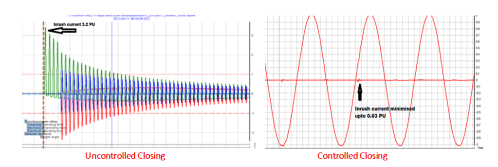
The waveform shown below shows the difference of inrush current value with controlled switching and uncontrolled switching. Using the CSD we have minimized the inrush current from 3.2 PU to 0.03 PU.
Summary
In this manner, controlled switching technique can be used to prevent disturbances and over voltage’s which may result in failure or reduction in lifespan of power transformers, shunt reactors and capacitor banks. The concomitant failure from disturbances can lead to power system stability issues, with major consequences for network operators such as Central Transmission Utilities and State Transmission Utilities. In our next blog post, we will showcase how SCOPE used controlled switching devices to protect 500 MVA ICT at a leading transmission utility’s 765/400 kV substation.
For more information on SCOPE marketed controlled switching devices, please visit https://www.scopetnm.com/protection-solutions/controlled-switching-device or write to us at marketing@scopetnm.com

One Reply to “”