

In the last two blogs, we have shared our knowledge on the technique of controlled switching to enhance the life expectancy of assets in the electrical network and improve system stability. By discussing how life span of reactors, capacitor bank assets and power transformers can be enhanced through controlled switching, we have underscored the criticality of this technique vis-à-vis the electrical network.
In this post, we will cover how SCOPE’s service company – ISOSCELES SALES & SERVICES PVT LTD (ISSPL) successfully installed controlled switching device (CSD) for 500 MVA ICT at a 765/400/220 kV substation.
https://www.windpowerengineering.com/controlled-switch-device-improves-medium-voltage-transformers-circuit-breakers/
The Challenge
A transmission licensee, one of the largest in India, began implementing the project which involved the construction of 765kV & 400kV substations along with 765kV single circuit & 400kV double circuit lines. The commissioning of two 765kV substations in this project was among the first instances of EHV voltages being commissioned by a licensee other than the Central Transmission Utility.
The project scope required the installations of Control Switching Devices (CSDs) at the 765kV and 400kV ICT and Reactors, however one 500MVA ICT at the substation was not provided with a CSD. During first charging of this 500MVA transformer, sparks were observed near the tank joint. The picture below describes the observed sparks:
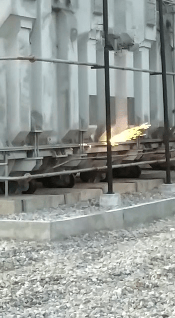
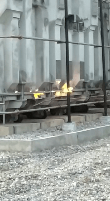
This persistent sparking represented a major danger as possible consequences included both safety and economic loss. A serious failure on the transformer could lead to premature retirement of the power transformer, possibly blasting of transformer causing damage to nearby assets and therefore the associated replacement costs, overall system failure and violation of service agreements entered into with the beneficiary licensees. Given the gravity of the problem, ISSPL was approached with a mandate to provide a solution to the problem.
The Solution
On examining the issue on the field and reviewing the case history, service experts at ISSPL concluded that the sparks observed were due to inrush current. In line with our experience with similar issues encountered by our customers, ISSPL recommended that a CSD be installed to rectify this persistent problem of spark on the transformer tank.
Thus, ISSPL installed SCOPE marketed CSD – SynchroTeq Plus on the 500 MVA ICT.
CSD Configuration Strategy
The service experts of ISSPL, bringing together their wealth of experience in providing innovative solutions, recommended that the technique of closing the first phase on the peak voltage be used. This is a widely used strategy which energises power transformers without considering the residual flux on the magnetic core.
During field tests, one of the CB poles was closed by SynchroTeq Plus CSD at peak voltage and other poles were closed simultaneously. The average inrush current was reduced with an average of 0.55 PU, an improvement of 250% over uncontrolled switching.
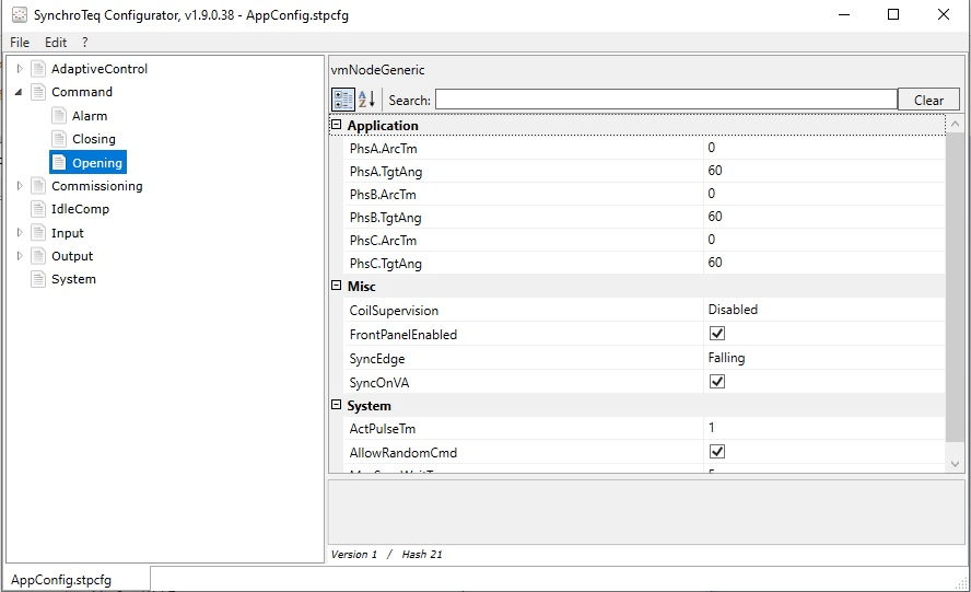
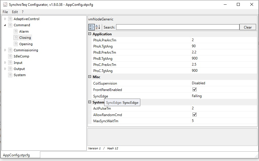
It should be noted that the peak inrush current resulting from this technique depends on the network topology. Reference setting files are shown below:
Results
During the first CLOSE operation, we found smooth operation in all 3 phases, on account of absence of residual flux in the transformer core. No spark was observed on the transformer tank.
To review, OPEN operation was done with the same settings and in the next CLOSE operation, we found 47Amp, 117Amp and 47 Amp (Peak) current in R, Y and B phase respectively. No spark was observed on the transformer tank due to very low value of inrush current.
Repeated operations were done to confirm consistency during which no spark was observed on the transformer tank due to very low inrush currents in all 3 phases. Given below are peak current values of last 4 CLOSE operations.
| Sr.no | Event No | R- Ph max peak current | Y-ph max peak current | B-ph max peak current |
| 1 | 235 | 15 A | 13A | 27 A |
| 2 | 237 | 64 A | 65 A | 27 A |
| 3 | 239 | 34 A | 32 A | 20 A |
| 4 | 241 | 34 A | 34 A | 50 A |
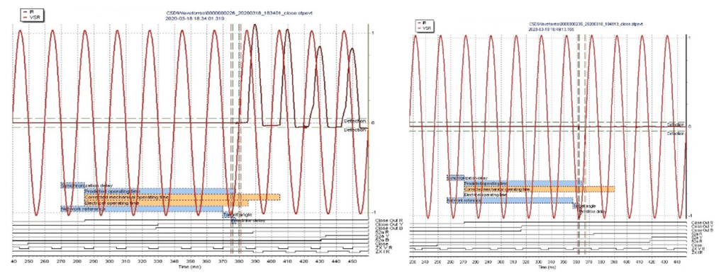
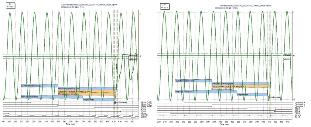
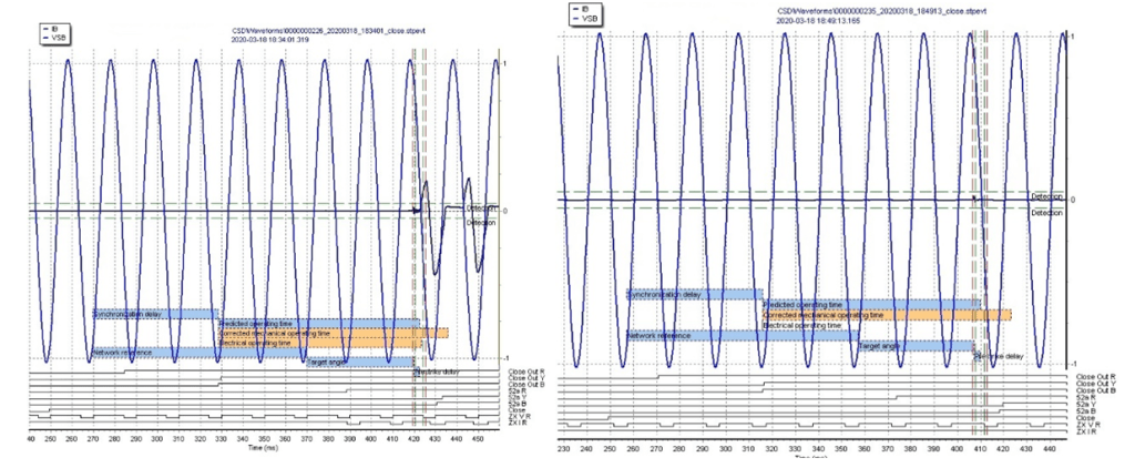
Given below are wave forms during uncontrolled and controlled switching:
Conclusion
Therefore, installation of CSD mitigated inrush currents and consequently, no spark was found during closing operation. Therefore, a persisting problem was solved and the life span of the transformer was enhanced.
To learn more about SCOPE marketed controlled switching devices, please visit https://www.scopetnm.com/protection-solutions/controlled-switching-device or write to us as marketing@scopetnm.com
