

In the previous blog we discussed the principle of cable fault pre-location and noted the criticality of this technique towards reducing the time taken to identify location of the fault. We also deliberated upon the various cable fault pre-location techniques.
In this blog post, we will continue our ongoing discussion on cable fault location by sharing our knowledge on cable route tracing and depth measurement, cable fault pinpointing and cable identification. We will also discuss means to repair & re-test after successful pinpointing and cable identification.
Cable Route Tracing
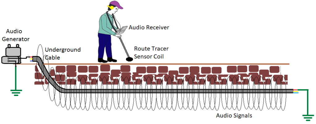
Often, pinpointing the cable fault takes larger time as the route tracing of the cable under test (CUT) has not been carried out or cable route is unknown. The exact route of the cable is determined by using audio induction method.
In the audio induction method, a stable, high frequency AC sinusoidal signal from an audio frequency generator is injected into the CUT at test end, which completes its path through earth and available on the entire cable lay. A route tracer sensor coil parallel to ground connected to an audio receiver picks up the signals, which is displayed on receiver visually in the form of graphs and in the form of sound captured through headphones.
Strongest signal is received exactly above the cable and signal strength reduces if the search coil is either side of the cable or away from it. The cable route is determined by finding maximum audio signals on audio receiver and headphones.
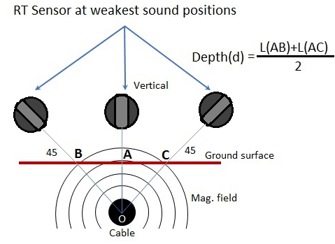
Cable Depth Measurement using Route Tracer System
In this method, the steps illustrated in the route tracing method above should be repeated. Keeping the route tracer sensor coil in the vertical position just above the cable gives a minima point (‘A’). Rotating the coil anticlockwise at angle of 45 degrees would result in a second minima point (‘B’); further rotation clockwise by another 45 degrees, would provide a final third minima point (‘C’). The depth of the cable at point A is half of the distance between points B & C.
Cable Fault Pinpointing
Based on the approximate fault distance calculated by Pre-locator and suspected faulty area marked by using route tracing procedure, the exact cable fault location or pinpointing of fault is carried out.
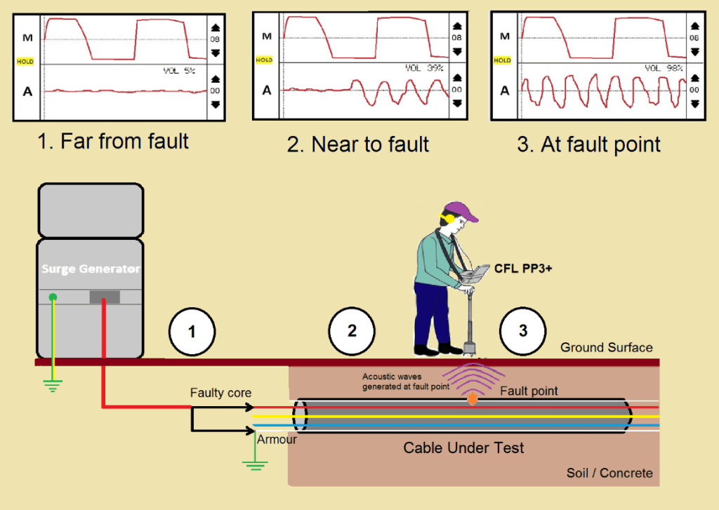
Pinpointing of High Resistance and Flashing Faults
For pinpointing high resistance and flashing faults, a HV surge is applied into the faulty cable periodically using surge generator, generating a thumping sound at the fault point and producing strong magnetic field around the cable. These acoustic and magnetic signals are picked with the help of PP Sensor (sensitive ground microphones) and displayed simultaneously on pinpointer receiver in the form of graphs and acoustic signals are heard on the headphones. Since both the signals, acoustic and magnetic are produced at the fault point simultaneously, the exact fault point is precisely located; where the time delay between them is near to zero. The magnetic field also helps user to determine the position of sensor and resulting easy pinpointing.
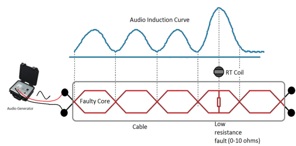
Pinpointing of Low Resistance (0Ω to 10Ω) Faults
Some faults having low resistance cannot be pinpointed by surge wave generator, as no thumping sound will be produced at a dead short fault point. For pinpointing such faults, audio induction method is used. A powerful audio frequency generator is connected across the faulty cores of the CUT. The signal travels up to the fault, emitting low signal. This signal is detected by the route tracer sensor coil and displayed on audio receiver. The signal will be present up to fault point, it will shoot up (max. signal at any sensor position) at exact fault point and dies out completely after a short distance.
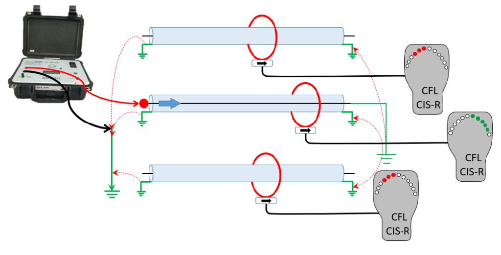
Cable Identification:
After excavation, identifying the appropriate cable from bunch of identical cables can be challenging. Cable identification is very important for safety of field personnel – cutting a wrong cable can result in fatal accidents. Hence cable identification system is required to identify the faulty cable.
A DC pulse transmitter / generator injects DC pulses from the test end on the core of the CUT. The far end of this core is grounded at far end, thereby making the return path of the pulse through metallic sheaths and armors of all the cables. When a receiver with current clamp is clamped around the cables, then the receiver detects current pulses and indicates wanted cable / unwanted cables based on current direction.
Repair & Re-test
After successful pinpointing of cable fault and the identification of faulty cable, it is essential to repair the same and re-test. This is done through the following steps:
- Discharge the CUT with discharge Rod
- Cut cable at the fault section
- Re-test both the sections for confirmation of free from faults, if present, pinpoint those faults
- Repair the faulty point / cable
- Post repair insulation test to be carried out on the full length of the cable
- Confirm that there are no more faults
- Carry out proof test on cable
- Clear for charging
While undertaking the entire process of pinpointing cable fault, identifying appropriate cable and repairing and re-testing, SCOPE experts ensure that all essential safety precautions are followed.
Conclusion
In this manner, cable fault location, cable route tracing and depth measurement, cable fault pinpointing and cable identification is done. By repairing and re-testing, we ensure that the underground cable fault is corrected; all the while ensuring safety of field personnel.
For more information on SCOPE cable fault locator capabilities, please visit https://www.scopetnm.com/test-and-measurements or check out our recent webinar on cable fault location on SCOPE’s YouTube channel. We also invite you to e-mail us at marketing@scopetnm.com for any queries, product quotations or services.

One Reply to “”