

In the previous blog post, we discussed how electrical utilities are using underground cables to gain a higher degree of reliability. However, underground cable faults can lead to a long downtime, which can further lead to a major revenue loss for electricity utilities. We also discussed the various causes of cable faults and the different types of cable faults.
In this blog post, we will discuss the various methods for underground cable fault location.
Cable Fault Pre-location
Determination of the distance of the cable fault (in meters or feet) from the test end is defined as pre-location of the cable fault. This is a critical aspect, as precise pre-location of the cable fault reduces the time taken for final fault location when compared to the conventional surge generator and pinpointed method. Pre-location uses low voltage methods such as time-domain reflectometer (TDR) and high voltage methods such as SIM, ARC, MIM, ICM/ICE & voltage decay method.
Pre-location using Time Domain Reflectometer Method
TDR method is used to pre-locate low resistance, short circuit, ingress of moisture and open circuit faults in the cable. It can also be applied to test the cable length and joints.
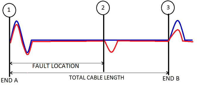
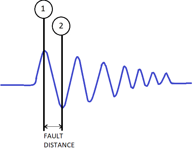
TDR method works on a principle similar to that of radar. A low voltage, the high-frequency pulse from pre-locator is injected to the cable under test. If the cable has constant impedance and is properly terminated, energy will be absorbed. If the pulse faces an impedance discontinuity/mismatch due to fault present on cable, part or all of the pulse energy is reflected back to the instrument. Pre-locator will measure the duration of the pulse transmitted, till the pulse is reflected back from the point of irregularity, i.e. Δt. If the fault distance is Lx, the velocity of propagation (VOP) is V, and the fault distance will be:
Lx=V*Δt / 2

Pic-2: Different types of TDR Graphs
Pre-location using Secondary Impulse (SIM), Arc Reflection (ARC) or Multiple Impulse Method (MIM)
Localisation of the cable faults with a high fault resistance is usually difficult using low-voltage TDR method. To localize these types of faults, the pre-locator needs to be used in conjunction with surge generator (thumper) and ARC / SIM filter. The essence of the arc reflection method is that: with the help of surge generator, a short-time electric arc is created at cable damage and this arc time gets prolonged by the use of ARC / SIM filter. Synchronously, the pre-locator performs the measurement. Thus, the high resistance fault is converted into a low resistance fault or short circuit fault; identified with the simultaneous application of TDR pulse by pre-locator. However, multiple signatures of ARC/SIM are taken in quick succession and compared to identify the fault location accurately.
Pre-location using Impulse Current Method (ICM/ICE)
In case of high resistance or flashing faults, the SIM / ARC / MIM method may not be able to give accurate results on account of the corroded cable sheath or damping of returned TDR signals. To overcome this, the current transient method known as impulse current method (ICM or, ICE) is used and preferred for longer cables. In ICM / ICE mode, the pre-locator is used in conjunction with the surge generator. Pre-locator and surge generator are then coupled to each other. During flash-over at the fault, current transients are generated. These oscillate back to the source, sensed through the current coupler and displayed on pre-locator for further analysis of fault distance.
Pre-location using Voltage Decay Method
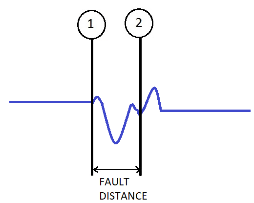
When the surge generator cannot breakdown at the fault point, then a DC high voltage is applied gradually in the test cable, until the high resistance fault breaks down. At the breakdown, the energy stored in cable gets discharged through the fault and generates voltage transients that travel back and forth to the test set from fault point with a repeated change in polarity. This process continues till the cable completely gets discharged. Pre-locator captures these voltage transients in passive mode with the help of a voltage decay coupler.
To determine the location of the fault, cursors are positioned at consecutive peaks of the trace to get the fault distance.
Conclusion
In this way, various methods for cable fault location are used based on the type of fault. In the next blog, we will continue the on-going series on cable fault mitigation by discussing the importance of the Cable Route Tracing System followed by cable fault pinpointing and cable identification.
For more information on SCOPE cable fault locator capabilities, please visit https://www.scopetnm.com/test-and-measurements or check out our recent webinar on SCOPE YouTube’s Channel on Cable Fault Location. You may also write to us at marketing@scopetnm.com for any technical queries, product quotations or services.

One Reply to “”