

Introduction
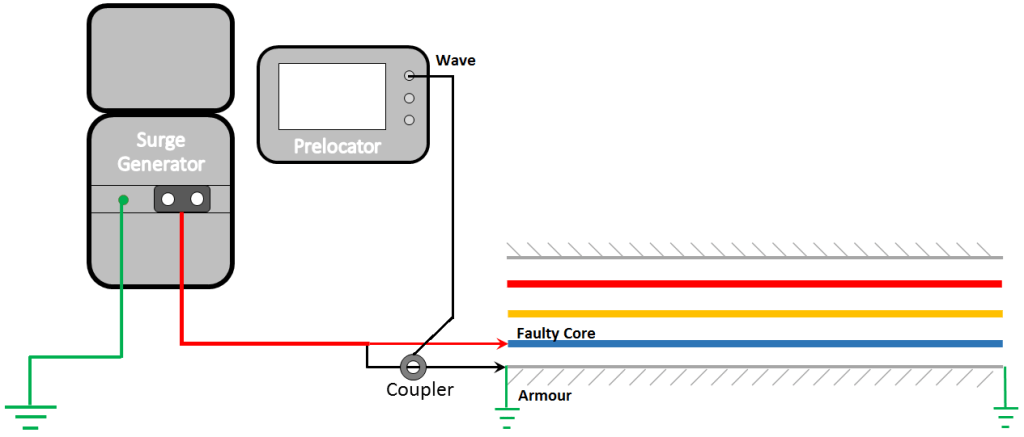
In the last blog, we discussed the SIM/ARC method used for the prelocation of the Insulation Failure / High Resistance faults. Taking the momentum forward we would discuss about the method to find out the distance of insulation failure / High Resistance faults in MV to EHV power cables, which are very long or consist of corroded armour/shield Impulse Current Method (ICM/ICE) is used. In ICM / ICE method, the Prelocator need to be used in conjunction with the Surge Generator (Thumper). The prelocator and Surge Generator get coupled to each other with the help of a current coupler or a small CT. When an HV Surge is applied across the faulty pair of the Cable using Surge Generator/ Thumper, a momentary breakdown or flashover will occur at the fault point. Due to this momentarily short circuit will occur, and current transients will be generated which will oscillate back to the source end. These transients will be sensed through a current coupler and would be displayed on Prelocator connected to it, for further analysis of fault distance. In this blog, we will discuss the test procedure and analysis of the ICM method.
Connections for ICM Test
- Identify the wanted cable terminations at both ends. Discharge all the cores for soft discharge followed by hard discharge with a tested discharge rod.
- Remove cable ends from terminals and bring them in the air, suitably away from each other.
- Ensure the Armour / Sheath of the Cable is grounded from both ends.
- Identify faulty core and measure the fault resistance with the help of an Insulation Resistance Tester.
- First connect the master earthing cable to the Master Earthing Terminal of the Surge Generator. The other end of the cable should be connected to the earthing strip/earth pit.
- Connect auxiliary Earth Cable to Aux. Earth Connector of Surge Generator. Insert the Earth Spike in the soil and pour water around it. Insert the earth spike as deep as possible for better detection.
- Connect the HV Output Cable of the Surge Generator to the Faulty Cable as shown in Fig.1.
- Clamp the Current Coupler on the HV Earth Lead (black) of the Surge Generator.
- Connect the Current Coupler to the Prelocator with the help of a BNC- BNC Cable.
- Connect the Mains Supply Cable to Surge Generator and then to a Single phase, 230V, 50Hz AC Receptacle.
Operations for ICM Test
- After successful connections, select the ICM/ICE mode in the Prelocator instrument.
- Set ‘Velocity of Propagation’ in the parameters setting as per the Cable Under Test.
- Select the proper settings of amplification/gain and set the measuring range 3 to 4 times of total cable length.
- Turn ON the Surge Generator and apply a manual impulse of 2kV or 3kV more than the breakdown voltage of the fault (detected previously). The current transients produced due to the breakdown of the fault are captured by Current Coupler and displayed on the Prelocator. Confirm the repeatability of the waveform 2-3 times.
- Perform cursor measurements and analyse the resulting waveform (Refer to the table of ICM Graphs). If necessary, save the waveform into the device’s internal storage.
- Note down the observations in Cable Log Sheet.
Types of ICM Graphs
Fault Distance Measurement in ICM Method
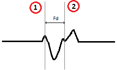
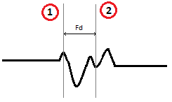
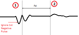
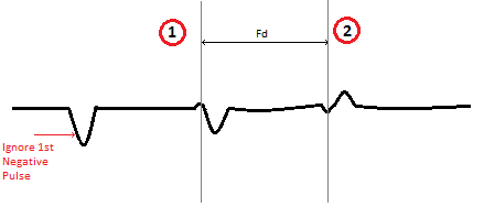
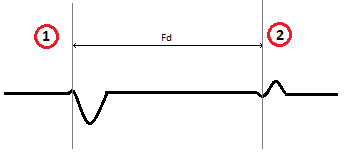
In the ICM method, a graph of current transients will be plotted on Prelocator. Since the transients are generated from the fault point, the negative reflection shown in the above sample graphs is representing the fault point (refer to cursor 1) and the hump-type shape after the negative reflection is representing the test end i.e., the location of CT refer cursor 2). Perform the cursor measurements (cursor 1 & 2) as shown in the sample graphs from the above table for determining fault distance using ICM Method.

Conclusion
In this blog, we discussed the ICM method of Prelocation for High Resistance/Insulation Failure Faults. ICM and SIM Methods cannot be used to locate the faults in EHV Cables having breakdown voltage greater than the Surge Generator’s voltage injection capabilities (generally above 32kV). For this type of application, a voltage transient method i.e., the voltage decay method is used to prelocate the fault distance. In the next blog, we will continue the ongoing series of Prelocation and discuss the Voltage Decay Method.
For more information on SCOPE cable fault locating capabilities, please visit https://www.scopetnm.com/test-and-measurements or write to us at marketing@scopetnm.com.

One Reply to “”