

Introduction
In our earlier blogs, we discussed the prelocation using the Time Domain Reflectometry (TDR) method, for faults like low resistance, short circuit, ingress of moisture, and open circuit faults. Insulation failure / High Resistance faults cannot be determined using a low voltage source of a TDR or Prelocator instrument. In Mid Voltage (MV) to Extra High Voltage (EHV) power cables, most of the time insulation failure faults are occurring and are difficult to locate. To find the distance of such faults a combination of Low Voltage TDR Pulse and High Voltage Impulse is used, called as Secondary Impulse Method (SIM) or Arc Reflection Method (ARC).
In SIM/ARC method, the Prelocator need to be used in conjunction with the CFL SG Series High Voltage Surge Generator (Thumper) and ARC / SIM filter. The essence of the Arc Reflection Method is that with the help of High Voltage Surge Generator/Thumper, a short-time electric arc is created in the place of cable damage and this arc time is prolonged using ARC / SIM filter. Synchronously with this arc, the Prelocator performs the measurement. Thus, we can transform the high-resistance fault into a low-resistance fault or short circuit fault and the fault location can be easily identified with the simultaneous application of TDR by Prelocator. However, to achieve this, the Prelocator needs to be coupled properly with the Surge generator and ARC / SIM filter in ARC / SIM mode. Multiple signatures of Arc Reflection Method (ARC) or, Secondary Impulse Method (SIM) are taken in quick succession and they are compared together to identify the fault location most clearly. It is known as Multiple Impulse Method (MIM).
In this blog we will discuss the Connections, Test Procedure, and Analysis of the SIM/ARC method.
Connection of SIM Test
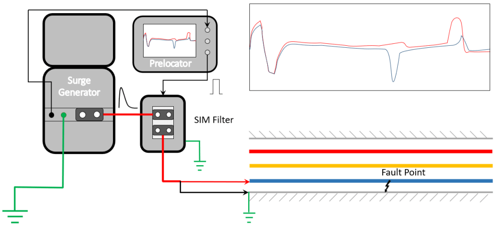
Fig.1 Connections for Secondary Impulse Method (SIM/ARC)
- Identify the desired cable terminations at both ends. Discharge all the cores for soft discharge followed by hard discharge with a tested discharge rod.
- Remove cable ends from terminals and bring them in the air, suitably away from each other.
- Make sure the Armour / Sheath of the Cable is grounded from both ends.
- Identify the faulty core by conducting Diagnosis Procedure (Continuity, IR Testing etc.).
- First connect the Master earthing cable to the Master Earthing Terminal of the Surge Generator. The other end of the cable should be connected to the earthing strip/earth pit.
- Connect Auxiliary Earth Cable to Aux. Earth Connector of Surge Generator. Insert the Earth Spike into the soil and pour water around it. Insert the Earth Spike as deep as possible for better detection.
- Connect the master earthing cable to the Master Earthing Terminal of SIM FIlter and another end of the cable to the earthing strip/earth pit.
- Connect the High Voltage (HV) Cable between Surge Generator’s HV Output to the HV Input of the SIM Filter.
- Connect HV Output Cable from SIM Filter to Cable Under Test.
- Connect the TDR port of the Prelocator to the SIM Filter and Trigger port to Surge Generator as per shown in Figure 1.
- Connect the Mains Supply Cable to Surge Generator & CFL SIMF+ and then to AC Receptacle.
Operation for SIM/ARC Test
- Turn ON the Surge Generator and SIM Filter. Apply an HV surge in the cable with an increment of 0.5kV in the applied voltage to determine the exact breakdown voltage. After the successful breakdown, turn OFF the Surge Generator
- Select SIM mode in Prelocator and set the proper velocity of propagation as per the Cable Type
- Turn ON the Surge Generator and apply a manual impulse of 1kV or 2kV more than the breakdown voltage of the fault (detected previously). At the moment of ignition, of the electric arc at the fault point, the Prelocator will perform the measurements and plot two TDR graphs in different colors
- Perform cursor measurements and analyze the resulting waveform and the point of the breakdown waveform will look like a typical short circuit
- Compare waveforms before the breakdown and at the time of the breakdown. If necessary, save the waveform into the device’s internal storage
Fault Distance Measurement in SIM Method
In SIM/ARC method, two TDR graphs are plotted on Prelocator Instrument. The first graph is plotted (refer to the blue colour graph) before applying surge and the second graph is plotted (refer to the red colour graph) above the 1st graph captured which is during the arc ignition at the fault point. The momentary Short Circuit during arc ignition is captured in the 2nd graph and a negative reflection indicating the fault point will be observed on the same. Perform the cursor measurements (cursor 1 & 2) as shown in figure 2 for determining fault distance.
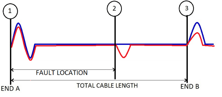
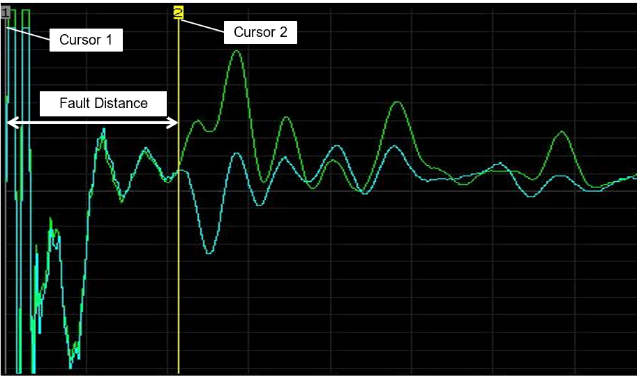
Fig.2 Sample graph of SIM Method
Conclusion
In this blog, we discussed the simplest method of Prelocation for High Resistance/Insulation Failure Faults. This method is not effective for cables which are very long or have corroded armour/shield due to damped TDR reflections. To overcome these limitations, a current transient method is developed called as Impulse Current Method. In the next blog, we will continue the ongoing series on Prelocation and discuss the ICM Method.
For more information on SCOPE cable fault locating capabilities, please visit https://www.scopetnm.com/test-and-measurements or write to us at marketing@scopetnm.com.
