

Energy is a critical facet for human development. Studies evaluating the linkage of electricity and GDP growth estimate that 1% increase in per capital energy consumption results in an increase of per-capita GDP by 0.23%. Given this centrality, development of electricity infrastructure has been a key focus area for governments and policy makers.
Power transmission and distribution was traditionally done through OHL (overhead lines) but these OHL lines are susceptible to damage due to environmental factors such as heavy wind and lightning. Thus electrical utilities are now preferring to dig trenches and bury power cables (underground cables) into the ground in order to gain a higher degree of reliability for power transmission and distribution. However, underground cables also suffer from faults and because of its buried status without proper markings, these faults generally take a long time to detect resulting in long downtime. These long outages can cause major revenue loss to electricity utilities, heavy production loss for industries and cause major inconvenience to customers.
In this blog post, we will share our knowledge on the causes of cable faults, types of cable faults and classification of cable faults.
Underground Power Cables
A Power Cable is an assembly of one or more electrical conductors surrounded with electrical insulation, usually held together with an overall plastic sheath used to transmit the electrical power. Typical construction of a power cable is shown below:
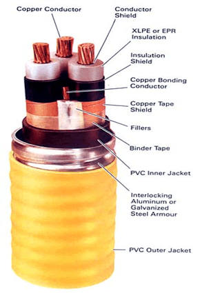
Figure 1: Construction of MV Power Cable
Causes of Faults
Faults occur in underground power cables occur due to the following reasons:
- Manufacturing defects such as voids, ‘fall in’ on conductor shield/insulation interfaces etc.
- Poor workmanship during cable laying (excessive pulling tension, exceeding minimum bending radii)
- External mechanical damage (road widening, construction, infrastructure development etc.)
- Earth subsidence
- Overloading/over voltage events
- Lightning strike, sheath/armour corrosion
- Ingress of moisture, ageing
- Damage by termites or rodents, poor workmanship while conducting repairs etc.
Types of Cable Faults
There are 6 major types of cable faults, as summarized below:
Open Circuit or Breaks in Cable: In this type of fault, one or all the cores of the cable break at a point, having infinite resistance between two ends. These breaks may be partial (few strands are open) or complete.

Contact Faults: A contact between one core (conductor) and another or between core(s) and the metallic sheath is called as Contact type of faults. The value of fault resistance varies between zero ohm to many mega ohms.

Flashing Fault: The cable withstands insulation test up to some level, beyond which it Flashes at a spot that acts like a spark gap. These types of faults occur due to the poor workmanship during installation / repairing of Cable Joints & Terminations or ageing.

Ground Contact Fault: This fault is also called as earth fault or sheath fault. Any Core or metallic sheath or armour of the cable comes in contact with mass of earth due to external damage on outer sheath cover.

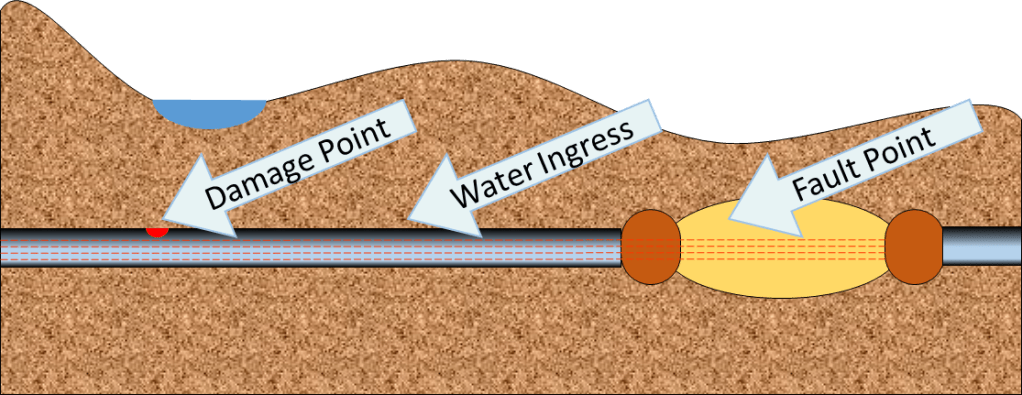
Ingress of Moisture: Water enters into cable at some point of damage and remains inside it. This will lead to the formation of water trees in cable insulation. Under the application of working voltage, these water trees get converted into electrical trees and results in insulation breakdown.
Thus, we have reviewed the causes of underground cable faults and the types of underground cable faults. The table below illustrates the classification of faults based on resistance:
| Faults | Classification based on resistance |
| Short circuit/earth fault | <10Ω |
| Low resistance fault | <100KΩ |
| High resistance/flashing faults | >100KΩ |
| Open circuit faults | >1000GΩ |
| Wet faults | Unstable IR Value |
Methodology for Locating Cable Faults
In this section, we discuss the methodology for locating cable faults.
Short Circuit Fault Location
- Continuity of each pair (Core-Core, Core-Armour) by keeping both the cable ends open is checked by a multimeter. Pair with continuity will be identified as faulty
- Cable length and fault distance is determined with TDR method using prelocator
- Audio Frequency Generator is connected to the faulty pair of the cable under test (CUT), the cable route is traced with suitable Receiver till the last Signal Peak (fault Point) and after this signal dies out completely.
- After digging, identify the faulty cable from bunch of cables, if applicable, with the help of Cable Identification System.
- The faulty cable is to be identified, and the faulty section repaired.
Low/high resistance/flashing fault location
- After the faulty pair and faulty resistance is identified, the total cable length is determined by TDR method
- Fault distance is determined with ICM or SIM/ARM method and exact cable route is marked at Prelocated distance
- The exact fault location is pinpointed with the help of Pinpointing Set using Coincidence Method.
- The faulty cable is identified from a bunch of cables and the faulty section is repaired.
Open circuit fault location
- After continuity of each pair is checked by multi-meter, the total cable length and fault distance is determined with Time Domain Reflector method
- Audio Frequency Generator is connected to the healthy pair of the faulty cable and cable route is traced with suitable Receiver
- The faulty cable is identified from a bunch of cables and the faulty section repaired
Wet/moisture ingress fault location
- With the help of Insulation Resistance Meter, find out faulty pair (Core-Armour) having unstable IR readings by keeping both the cable ends open.
- Dry out the wet faults using Pre-conditioning techniques such as Surging for few minutes via Surge Generator (Thumper) or Burning (Apply Continuous HV DC) via Burn-down set or by charging the CUT for a moment.
- Follow the steps as mentioned in Low / High Resistance Fault Location.
Summary
Thus, cable faults can be identified and located through above methodology. In the next blog, we will share our knowledge on cable fault pre-location methods and cable route tracing and depth measurement.
For more information on SCOPE cable fault locator techniques, please visit https://www.scopetnm.com/test-and-measurements or write to us at marketing@scopetnm.com. Please also visit out youtube channel for our recent webinar on Underground Cable Fault Location: https://youtu.be/MTcNNNQUqxo

Great initiative of Blog for cable fault location techniques. We at MSEDCL have long rapport with scope.
Feel good about joining the blog
LikeLike
Sir we are also feeling happy to know that you are now following our blog content.
LikeLike
Great initiative of Blog for cable fault location techniques. We at MSEDCL have long rapport with scope.
Feel good about joining the blog
LikeLike