

Introduction
In the previous blog, we discussed the ICM method used for prelocation of the Insulation Failure / High Resistance faults. To find out the distance of insulation failure / Very High Resistance faults in HV to EHV power cables, in which the breakdown voltage is greater than the Surge Generator’s voltage the Voltage Decay Method (ICM/ICE) is used.
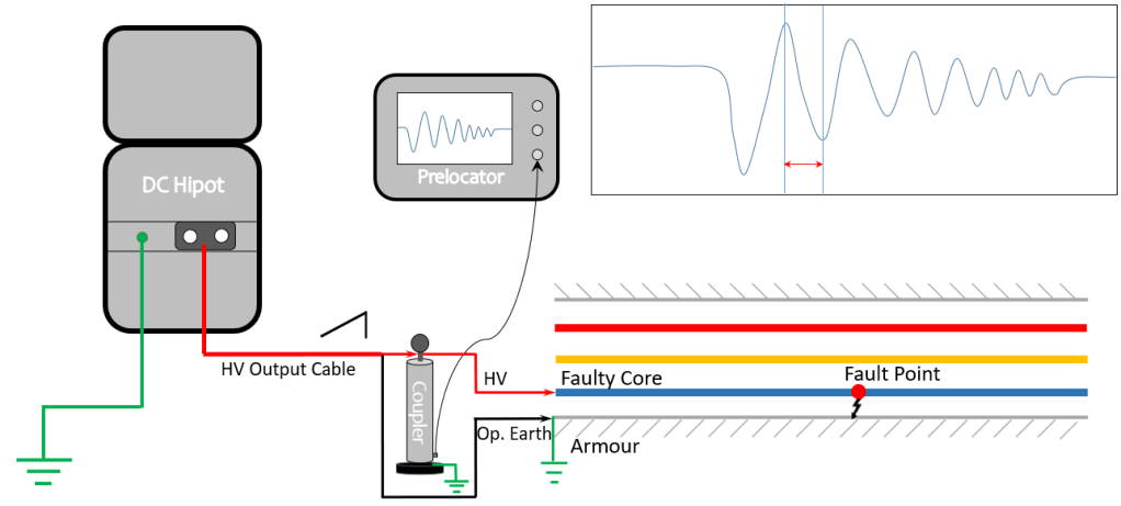
In the Voltage Decay method, the Prelocator needs to be used in conjunction with a DC High Voltage Tester (DC Hi-pot) instead of a Surge Generator, used in previous ICM and SIM methods. The prelocator and DC Hi-pot get coupled to each other with the help of a Voltage Decay coupler. The output of the Voltage Decay coupler is connected to Prelocator. A gradually increasing DC High Voltage will be applied using a suitable DC Hi-pot, the cable under test will act as a capacitor and it will be charged due to the injection of DC Voltage. After a particular voltage level, the fault breaks down and the charged cable starts discharging itself across the fault point. This will create voltage pulses (transients) that travel back to the Hi-pot end, where it gets reflected to the fault point. When the same pulse reaches back to the fault point, its polarity gets reversed and it again travels back to the test set. This process continues until the cable completely gets discharged.
In the Voltage Decay Mode, the Prelocator does not send any pulse into the cable but, operates in passive mode, just like an oscilloscope and captures the back-and-forth voltage transient signals with the help of a Voltage Decay Coupler. These transients will be displayed on Prelocator for further analysis of fault distance. In this blog, we will discuss the test procedure and analysis of the Voltage Decay method.
Connections for Voltage Decay Test
- Identify the wanted cable terminations at both ends. Discharge all the cores for soft discharge followed by hard discharge with a tested discharge rod.
- Remove cable ends from terminals and bring them in the air, suitably away from each other.
- Ensure the Armour / Sheath of the Cable is grounded from both ends.
- Identify faulty cores and measure the fault resistance with the help of an Insulation Resistance Meter.
- First connect the master earthing cable to the Master Earthing Terminal of the DC Hi-pot. The other end of the cable should be connected to the earthing strip/earth pit.
- Connect Earthing Cable from the Master Earthing Terminal of the Voltage Decay Coupler and then to the earthing strip/earth pit.
- Connect Auxiliary Earth Cable to Aux. Earth Connector of DC Hi-Pot. Insert the Earth Spike in the soil and pour water around it. Inset the Earth Spike as deep as possible for better detection.
- Connect the HV Output Terminal of the DC Hi-pot to the HV terminal of the Voltage Decay Coupler as shown in Figure 1.
- The HV Terminal of the Voltage Decay coupler is connected to the faulty core of the Cable using a HV cable as shown in Figure 1.
- Connect the Operational Earthing Cable directly to the Armour (Shield) of the cable.
- Connect the Voltage Decay Coupler to the Prelocator with the help of BNC Cable.
- Connect the Mains Supply Cable to Surge Generator and then to a 230V, 50Hz AC Receptacle.
Operations for Voltage Decay Test
- After successful connections, select the Voltage Decay mode in the Prelocator instrument.
- Set ‘Velocity of Propagation’ in the parameters setting as per the Cable Under Test.
- Select the proper settings of amplification/gain and set the measuring range 3 to 4 times of total cable length.
- Turn ON the DC Hi-pot, desired trip current and apply the voltage in a gradually increasing manner.
- When the fault will break down, the voltage transients will be produced and captured by Current Coupler and displayed on the Prelocator. Confirm the repeatability of the waveform 2-3 times.
- Perform cursor measurements and analyse the resulting waveform. If necessary, save the waveform into the device’s internal storage.
- Note down the observations in Cable Log Sheet.
Fault Distance Measurement in Voltage Decay Method
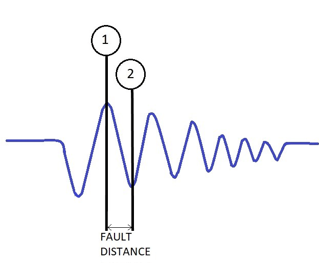
In the Voltage Decay method, a graph of voltage transients will be plotted on Prelocator. Put cursor 1 at the first positive peak of the waveform and cursor 2 at the successive negative peak to get the fault distance using the Voltage Decay Method.
Conclusion
In this blog, we discussed about the Voltage method of Prelocation for High Resistance/Insulation Failure Faults. With this blog, the blog series of Prelocation is completed. Stay tuned to our Website for the upcoming knowledge-packed blogs about the Power Cable Fault Location.
For more information on SCOPE cable fault locating capabilities, please visit https://www.scopetnm.com/test-and-measurements or write to us at marketing@scopetnm.com.
