

In an earlier blog, we discussed the techniques and methodologies for health assessment of lightning/surge arresters. We also shared our knowledge on the various methods of measuring resistive leakage current or power loss. In the following blog, we answered the 10 most frequently asked questions on the various aspects of testing and measuring lightning/surge arresters.
Thus, we explained the offline methods of health evaluation of surge arresters (Tan delta test, Insulation resistance test & AC leakage current) and the online method (Third Harmonic Resistive leakage current analysis) along with the other methods defined by IEC 60099-5. In this blog we will explain the significance of the leakage current of surge arrester and discuss effective techniques for health evaluation of GIS surge arresters.
Types of Stress Impacting the performance of Surge Arresters:
Typically, the following factors impact the operation of the surge arresters:
- Normal operating voltage,
- Overvoltage due to improper switching,
- Temporary overvoltage,
- External lightning
- Environmental conditions
These types of stress, either individually or together in different combinations may decrease the dielectric strength of the insulation and as a result, cause a significant rise in leakage current. This leakage current can be divided into two parts:
- Capacitive Leakage current: mostly constant.
- Resistive Leakage current: often affected by the types of stress mentioned above and as a result, increases.
On account of the increase in resistive leakage current, the total leakage current also increases. Therefore, it can be said that resistive leakage current is a significant parameter; and the measurement of resistive leakage current flowing through surge arresters at the normal condition gives the information about the actual operating condition. This is advantageous in the following ways:
- Prevents failures of surge arrester by replacing them with new one
- Avoids disturbances due to the breakdown of arresters in the electric power supply
- Increases the safety of adjacent expensive equipment like Power Transformers, reactors, CT, PT etc.
- Maintains the safety of substation personnel
GIS Surge Arrester:
In the earlier blog the construction of surge arrester was explained in detail along with the equivalent circuit. As regards with the equivalent circuit, there is no major difference between Air Insulated Switchgear (AIS) & Gas Insulated Switchgear (GIS) surge arrester.
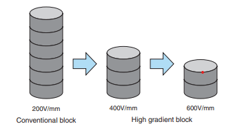
The design of the GIS surge arrester is a little different compared to the conventional AIS surge arresters. The gradient block (ZnO) has a high reference voltage per thickness hence it is possible to decrease the number of blocks and design a compact surge arrester. Below diagram is of image of block use between conventional blocks (Used in AIS) and high gradient blocks (Used in GIS).
Importance of Voltage peak method:
For measurement of resistive leakage current of GIS surge arrester, third harmonic resistive leakage current method is not required. Voltage peak method as described in IEC 60099-5- A1 can be used.
In the AIS substation as PT secondary voltage which is proportional to line voltage is not available near the surge arrester. So resistive current measurement with voltage peak method (A1 method) is not possible. In this AIS third harmonic resistive leakage current is measured
The PT secondary voltage, which is proportional to applied line voltage, is easily available near the GIS surge arrester. It makes actual resistive current measurement possible in GIS surge arresters.
The resistive leakage current generated in the arrester is in phase with the line voltage. This says that the leakage current value at the time of voltage peak is actual resistive leakage current in the arrester. As PT voltage and leakage sensing is easily possible near GIS surge arrester, we are doing the leakage current analysis by voltage peak method as described in IEC 60099-5-A1 method.
GIS Surge Arrestor Health Monitoring:
The GIS surge arrester health monitoring can be done via resistive leakage current analysis using the voltage peak method, described in IEC 60099-5 as A1 method. In the voltage peak method, used to measure the resistive current, this resistive current depends on using a reference signal which represents the applied voltage to the arrester. This signal can be used for measurement of resistive component in the leakage current at the instance of voltage peak. Therefore, the value of current in the current signal, when reference voltage signal is at peak is the actual resistive current.
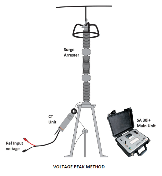
It should also be noted that in GIS surge arrester, the reference voltage is 110V AC signal. Reference signal is given to the phase of which the surge arrester is under testing. The CT is inserted in the earthing path of surge arresters. The current through the earthing path and reference voltage peaks are sampled at high frequency for one complete cycle. The current at the voltage peak is calculated. Like this, several cycles are sampled and average of calculated resistive current is displayed.
Conclusion
SCOPE SA 30i+ and SCOPE SA 30i are state-of-the-art leakage current analyzers designed for effective health monitoring of GIS surge arresters. These SCOPE manufactured, Make in India products are designed for effective operation in hostile electrostatic noise often found in EHV switchyards upto 765 kV. For more information, please visit https://www.scopetnm.com/test-and-measurements/item/75-sa-30i and https://www.scopetnm.com/test-and-measurements/surge-arrestor-testing-equipment/sa30i or write to us at marketing@scopetnm.com

It is very interesting and useful
LikeLike