

Over the years, power generation in India has grown manifold: installed capacity has increased from 1.36 GW in 1947 to 382.73 GW as on April 2021 (Source: CEA). Therefore, maintenance of generators is critical to ensuring uninterrupted quality power to the country. Apart from the generator, the HT transformer and the HT motors play a strategic role in the power generation industry. Any outage due to unexpected failures in generation can have catastrophic effects on the utilities and the stability of the power system as a whole. Therefore, techniques which put in place an effective asset management program to reduce probability of unexpected outages is of utmost importance.
In this blog, we will discuss the technique of conditional assessment of generators and the typical tests to be conducted under this mechanism.
What is Conditional Assessment?
Conditional assessment of electrical equipment in power plants is a mandatory requirement for a successful asset management program which seeks to minimize unexpected outages. Conditional assessment can also help identify causes of deterioration in performance of any electrical equipment. Furthermore, utilities can reorient their budgets in a scientific manner so as to address the asset most at-risk of failure.
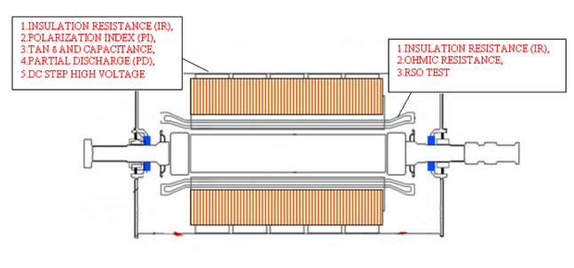
In case of a generator, reliable operation mostly depends on the condition of the stator winding insulation; hence, performing diagnostic tests has become mandatory. Service life of the generator depends on the behaviour of dielectric insulation available in the stator core, stator winding and rotor winding. Typically, the following tests are conducted on the stator and the rotor: a) insulation resistance test (IR), b) Polarization Index (PI) test, c) corona discharge (PD), d) Tan δ and e) capacitance and d) RSO tests conducted on the rotor side, as show in the figure below.
- Insulation Resistance (IR) & Polarization Index Tests
Electrical conductors in stator winding of turbine generators (TG) are insulated against grounded stator with high resistance micaceous composites to stop the flow of current outside the conductors. Deterioration of insulation system is eventual due to combined stresses, i.e., thermal, electrical, environment and mechanical. These stresses have consequences such as quality of the insulation changes, electrical resistivity reduces, leakage current through insulation volume increases, dielectric losses increase, hotspots and temperature increases, earth faults and inter turn faults occur and ultimately, accidental failure of TG occurs.
IR tests are conducted to know the integrity of insulation. A high order of resistance means very little current flow through insulation and low level of resistance signifies high current leaking through and along the insulation. It is carried out by applying lesser DC voltage than the rated voltage of TG.
IR is the quotient of the applied DC voltage across the insulation divided by the total resultant current at a given time. Circuit model of dielectric insulation is shown in the figure below. Components of currents viz. capacitance current (IC), resistive component (IR), leakage current (IS) and polarization current (IP) are flowing through bulk insulation during megger test.

- Capacitive current is the initial burst of current that occurs when voltage is first applied to a conductor. This transient current is initially high and falls near to zero exponentially in a few seconds when the insulation is fully charged
- Absorption current: Similar to capacitive current, absorption current starts out high and then drops. As the voltage builds up, the Absorption level in the insulation decreases. This gradual change reflects the storage of potential energy in and along the insulation. Incidentally, absorption current is an important part of the time resistance method of insulation testing.
- Leakage current is the small, steady, current present both through and over the insulation. Any increase in leakage current over time is usually an indication of deteriorating insulation.
While the first two current components decay with time, the third component is determined primarily by the presence of moisture or a ground fault and is relatively constant with time. If this leakage current is larger than the first two components, then the total charging current will not change significantly with time. Thus, to determine how dry and clean the winding, IR is measured after one minute and after 10 minutes. The ratio of the 10 minutes reading over the one-minute reading is called the polarization index (PI).
It is recommended that each phase be isolated and tested individually with respect to the same ground as the stator core or rotor body. Furthermore, a measurement of the insulation resistance is to be made with all external equipment disconnected and grounded.
Tan δ & Capacitance Measurement
Tan δ test will provide an overall indication of the dielectric losses and general status of general insulation system of the winding. Effect of partial discharge due to voids and stress grade erosion can be observed. By detecting changes in parameters such as capacitance, dielectric loss and power factor, failure hazards can be revealed, thereby reducing probability of loss of service.
In the test, insulation specimen having a low power factor as measured between its terminals can be represented equally by the parallel circuit of capacitance CP and resistance RP. For a specimen with zero power factor, i.e., low dissipation losses, is RP infinity.
Partial Discharge Test
We have previously discussed partial discharge testing in great detail. To summarize, partial discharges are electrical sparks that occur in voids within or adjacent to the insulation under high voltages. The high voltage stress in the air void causes sparks. In addition to the electrical stress, operating generators and motors are subjected to mechanical, thermal and chemical stress. Depending on the size of the void, the dielectric constant, and the temperature, the stress on the void may become high enough for complete breakdown to occur.
Digital RSO Test
A voltage impulse of 12 V dc is applied at positive terminal and the waveform is recorded at negative terminal. This is then reversed and an impulse of 12 V dc is applied at negative terminal and the waveform is recorded at positive terminal. The two waveforms are then superimposed and if the waveforms do not match, presence of faults in the rotor such inter-turn fault, high resistance joints earth fault etc., is indicated.
Conclusion
For more information on our generator condition assessment diagnostic testing capabilities, please visit https://www.scopetnm.com/substation-services or write to us at marketing@scopetnm.com

One Reply to “”