

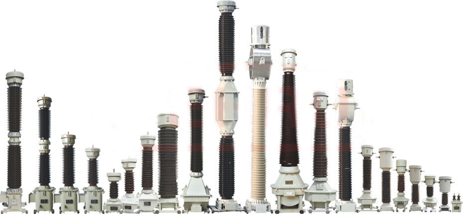
Instrument transformers are the important equipment of the power system. They are used to serve two main purposes i.e. measurement and protection. The instrument transformers which is used to reduce high currents flowing in power lines to the lower values for measurement and protection are called current transformer. The instrument transformers which is used to reduce the high voltages of power lines to the low voltages for measurement and protection are called potential transformer.
Tests conducted on Current Transformers:
There are two types of tests conducted on current transformers– Primary Injection Tests and Secondary Injection Tests. Primary injection tests mainly include ratio test by current injection method, excitation current test, phase angle error and polarity test. Secondary injection tests include ratio tests by voltage method, winding resistance tests, knee point voltage and secondary burden tests.
Primary Injection Test:
The primary injection test is frequently used to test the ratio of Current Transformers. It is recommended method by IEC 61869 1&2 to identify the current ratio of CT. It is simply injecting rated current through the P1 and P2 terminals of the CT being tested and measuring the generated current at the secondary terminals. The ratio between primary and secondary current is called the CT ratio.
For testing the ratio of the potential transformer, voltage is applied to the PT primary terminal and generated voltage at the secondary is measured. The ratio between primary and secondary voltages is called the PT ratio.
The Primary Injection Test is important to ensure that all the equipment and protection schemes are healthy and working as per the design. CT polarity is checked by Stability Test which can only be carried out with Primary Injection Test.
Secondary Injection Test:
A secondary injection test is conducted either by voltage method or by current method for checking the health of the CT secondary cores, protection relays, meters & protection scheme wiring etc. In the secondary injection test, voltage less than knee point voltage is applied to the CT secondary terminals and voltage generated at the primary side is measured. The ratio between the secondary applied voltage and the primary measured voltage is called the CT ratio.
In secondary current injection, the lowest current like 1 A is injected in protection scheme wiring for checking the wiring scheme and protection relay operation.
When to conduct primary and secondary injection tests?
Primary and secondary injection tests are important tests which are conducted during pre-commissioning testing of CTs and PTs and also during the periodic maintenance schedule of CTs and PTs.
If CT or PT undergoes any fault during its operation then we should conduct the primary and secondary injection tests to check the CT ratio and confirm the wiring healthiness.
Secondary winding resistance test:
CT secondary winding resistance test plays an important role in verifying the true condition, state and healthiness of the protection scheme. CT secondary winding resistance test also verifies the continuity of secondary core winding. The winding resistance of the CT secondary core can change based on the load, ageing of equipment and external climate conditions. It is advised to test the winding resistance of CT secondary winding periodically.
A low-value DC is passed through the CT secondary winding and the voltage drop is measured to calculate the winding resistance. As the winding resistance is a DC test, it is possible that the CT may get magnetized hence it is required to demagnetize the CT after completion of the winding resistance test
Burden Test
The burden of the current transformer is nothing but the total impedance or the total load on the secondary terminals of the CT. The total burden is the combination of the impedance of the relay coil, energy meter coil, inter-connection contact resistance, wire resistance and switches used in the secondary circuit. If a current transformer is not properly sized based on the secondary loop burden, it may result in a decrease in CT secondary current. Burden testing is important to verify that CT is supplying current to a circuit that does not exceed its burden rating.
With the burden test, we can ensure that,
- CT is not energized with shorting devices installed (if used for metering or protection)
- CT is not left open circuited, when not in use
- CT is connected with a single ground point
- All connections are tightened
Knee Point Voltage Test:
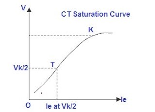
Knee Point Voltage of a Current Transformer is defined as the voltage at which a 10 % increase in voltage across CT secondary terminals, results in a 50 % increase in secondary current. Above knee point voltage, the output current does not follow the input current linearly. The following fig shows the CT saturation curve plotted as voltage v/s current and it shows the knee point voltage indicated by the letter K.
Test Procedure for Knee point Voltage Calculation of CT:
Apply 5-10 % voltage of the knee point voltage to the secondary of the CT by auto-transformer. Note down the secondary current. Increase the voltage gradually to 20, 30, 40, 50, 60, 70, 80, 90 % of the rated knee point of the CT and note down the secondary current. Plot a graph of applied voltage v/s measured current
Polarity Test:
The direction in which the secondary winding is wound on the core decides the polarity of the CT. Primary terminals of CT are marked with the P1 and P2 whereas secondary terminals are marked as S1 and S2. P1 is in line line-facing direction and P2 is in load facing direction. To check the polarity of any CT we need to inject the current through the primary winding from P1 to P2 and the secondary current will flow in the CT secondary winding. The direction of this current should be S1 to S2.
Insulation Resistance Test:
Every electrical equipment works on high voltage hence it should have proper and healthy insulation. In CTs, there is oil and paper insulation and it is required to check the strength i.e., insulation resistance periodically. While performing CT insulation resistance, three types of tests are performed-
- Primary to Secondary: To check the insulation between primary and secondary windings
- Primary to Ground: To check the insulation between primary and ground
- Secondary to Ground: To check the insulation between secondary and ground
The insulation resistance should remain constant during the lifetime of the equipment. A major fall in the IR value can lead to insulation failure and heavy power loss. The value of insulation resistance should be at least 1 Mega ohm per KV of the device under test. However, the trend of insulation resistance results should be monitored to understand the true health of the DUT.
Conclusion:
In this manner, CT PT health assessment and diagnosis are done through primary and secondary injection tests. The physical parameters like ambient temperature, humidity etc. also affect the testing results. A good primary and secondary injection tester can conduct all the above tests on instrument transformers. Other features like single-phase relay testing, software interface etc. can add more advantages. SCOPE has joined hands with Dynamics to offer primary and secondary injection test kits which can conduct all the above-mentioned CT tests and single-phase relay tests. For more information on products related to CT testing please write to us at marketing@scopetnm.com
